

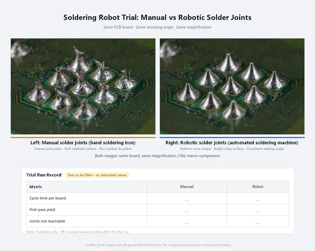
| Short answer: Robotic point-to-point soldering pays off when you have repeatable through-hole or wire joints, medium volumes and frequent product changes. Selective wave soldering wins at high volume with many through-hole joints per board. Hand soldering still makes sense for very low volume, rework, or joints a tip cannot reach. The deciding factors are joints per board, boards per shift and changeover frequency. |
After SMT, most electronics still need a back-end soldering step: through-hole connectors, transformers, terminals, wires and cables. In many factories this is still done by hand. Skilled soldering operators are hard to hire and hard to keep, joint quality varies from person to person, and more customers now ask for process records that a hand iron cannot provide.
Automation is the obvious answer, but "automate" can mean two very different machines: a soldering robot or a selective wave soldering machine. This guide compares the three options in neutral terms, gives you five questions that decide the answer and a payback worksheet you fill in with your own numbers, and explains how to run a fair trial before you buy.
Three ways to solder after SMT
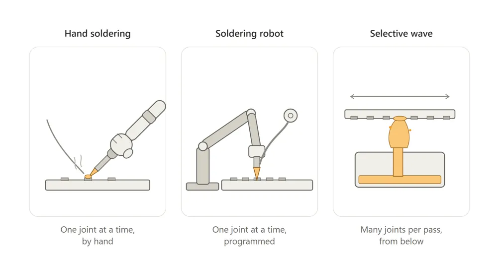
• Hand soldering. An operator uses a soldering iron and solder wire on one joint at a time. Very flexible, with almost no setup, but the result depends on the person, the shift and the day.
• Robotic point-to-point soldering. A multi-axis robot moves a soldering iron and an automatic wire feeder from joint to joint. It does what a skilled operator does, one joint at a time, but with the same temperature, feed and time on every board.
• Selective wave soldering. The board passes over a small fountain of molten solder through a programmed path, after fluxing and pre-heating. It solders many through-hole joints in one pass. See the selective soldering overview for the process steps.
Traditional full wave soldering still exists for boards that are mostly through-hole, but on modern mixed-technology boards it usually needs masking pallets to protect SMT parts. That is why the practical choice for back-end soldering is usually between the three methods above.
Hand soldering vs soldering robot vs selective wave: comparison table
| Factor | Hand soldering | Soldering robot | Selective wave |
| Best-fit joints | Rework, odd parts, joints hard to reach with a fixed program | Through-hole leads, connectors, terminals, wire-to-board joints soldered from the top | Boards with many through-hole joints soldered from the bottom side |
| Volume | Very low to low | Low to medium; scales by adding robots or platforms | Medium to high |
| Changeover | Instant | Load a stored program and swap the fixture | Program plus nozzle, flux and pre-heat settings; longer to prove a new board |
| Thermal stress on the board | Local, but varies by operator | Local and repeatable | Board pre-heated and bottom side exposed to solder; needs process tuning |
| Joint consistency | Depends on operator skill | Repeatable once the program is proven | Repeatable once the process window is set |
| Flux residue | Flux-cored wire; residue varies | Flux-cored wire; local residue only | Applied flux over joint areas; may need cleaning depending on flux |
| Investment level | Lowest | Moderate | Highest of the three |
| Floor space | A bench | A bench or a space on the line | A dedicated in-line machine |
| Operator skill | Skilled soldering operators | Loading plus a technician for programming | Process engineer plus operators |
| Process records | Manual, if any | Program and parameters per joint are stored | Program and process settings are stored |
In short: a soldering robot replaces the hand iron joint for joint, and selective wave replaces many joints with one pass. The more through-hole joints per board and the more boards per shift, the more selective wave makes sense. The more models and changeovers, the more a robot makes sense.
Five questions that decide the answer
• How many joints per board? A handful of connector pins and wires suits a robot. Dozens or hundreds of through-hole joints on the bottom side point to selective wave.
• How many boards per shift? Multiply joints per board by boards per shift. That number, compared with the cycle time per joint you measure in a trial, tells you how many robots you would need.
• How many models and how often do you change over? High-mix lines with daily changeovers favour robots, because a new board is a new program and a fixture.
• Can a tip reach every joint? Tall components, shields and housings can block a soldering iron. Joints on the bottom side, or under large parts, may suit selective wave or stay manual.
• What records do your customers expect? If audits ask for process parameters per product, a programmed method gives you stored settings that hand soldering cannot.
| If your answers look like this | Lean toward |
| Few joints per board, many models, frequent changeover | Soldering robot |
| Many through-hole joints per board, few models, high volume | Selective wave |
| Very low volume, prototypes, rework | Hand soldering |
| Wire-to-board or cable joints, top-side access | Soldering robot (wire soldering model) |
| Mixed: a few joints a tip cannot reach on an otherwise robot-friendly board | Robot plus a short manual touch-up station |
A simple payback worksheet
We do not publish a payback period or an efficiency multiple, because they depend completely on your joints, your wages and your quality costs. You can work it out yourself in ten minutes with this worksheet. Use monthly figures.
| Line item | How to estimate it | Your number |
| A. Current labour cost | Soldering operators per shift × shifts × monthly cost per operator (wage, overtime, benefits, hiring and training) | |
| B. Current rework and scrap cost | Boards reworked per month × rework cost per board, plus scrapped boards | |
| C. Labour cost after automation | Operators still needed for loading, inspection and touch-up × shifts × monthly cost | |
| D. Rework cost after automation | Estimate from your trial first-pass yield | |
| E. Running cost of the machine | Tips, cleaning consumables, maintenance, power | |
| F. Monthly saving | (A + B) − (C + D + E) | |
| G. Investment | Machine(s), fixtures, programming, installation, training | |
| Payback in months | G ÷ F |
| Fill in rows C and D only after a trial on your own board. Estimates based on brochures, including ours, are not a substitute for a measured cycle time and first-pass yield. |
Desktop vs in-line soldering robots
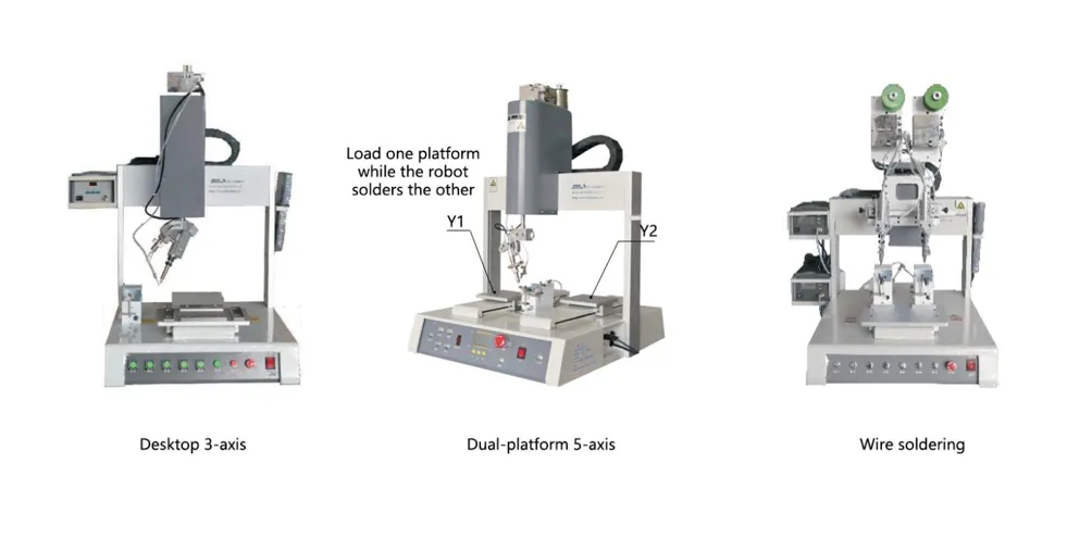
Soldering robots come in two broad forms. Desktop machines sit on a bench, and the operator loads a fixture by hand. Some desktop models can also be placed directly on a production line. Dual-platform machines add a second Y-axis table, so the operator loads one table while the robot solders on the other; this hides most of the loading time. Conveyor-integrated machines take the board straight from the line and suit higher volumes with fewer models.
Our soldering range covers the desktop and dual-platform forms:
| Model family | Form | Axes and platforms | Working area (per product page) | Typical use |
| XH-T3311 / T4411 / T5511 / T53311 | Desktop, single head; can be placed on a production line | 3 axes, optional R axis; T53311 has dual Y tables | X 300–500 mm, Y 300–500 mm, Z 100 mm | PCB, connectors, FFC/FPC, LED products |
| XH-AS300 / AS400 | Desktop PCB soldering machine | 3 axes | 300 × 300 × 100 mm / 400 × 400 × 100 mm | Through-hole and connector soldering on PCBA, high-mix batches |
| XH-AS4002Y | Dual-platform robot | 5 axes, R 360° | X 400 mm, Y1/Y2 400 mm, Z 120 mm | Mixed boards needing per-joint parameters and angled joints |
| XH-S series (6 models) | Wire soldering machine | 4- or 5-axis control, R 360° on most models | 400 × 400 mm to 600 × 600 mm | LED strips, data cables, wire-to-board joints |
Where soldering robots struggle
A fair comparison has to include the cases where a robot is not the best answer:
• Very large thermal mass. Heavy busbars, large terminals and joints tied to thick copper planes may need more heat than a soldering tip can deliver in a reasonable time. Selective wave, with board pre-heat, often handles these better.
• Very dense through-hole fields. A board with hundreds of through-hole joints will take a long time point by point. That is where selective wave earns its higher investment.
• Joints a tip cannot reach. Tall or shielded components can block the iron. Check access on the real assembly, not on the bare board.
• Unstable incoming parts. Bent leads, varying wire strip length or poor solderability cause defects that a robot repeats faithfully. Fix the incoming material first.
RangJin Intelligent does not build selective wave soldering machines. If your board clearly belongs in the selective wave column, we will say so.
How to run a fair trial
A trial is the only reliable way to fill in the worksheet. Make it fair by keeping everything constant except the soldering method:
1. Use boards from the same batch and the same solder wire for hand soldering and for the robot.
2. Record the cycle time per board, including loading and unloading, not only the soldering time.
3. Inspect every joint against the same acceptance criteria, and record first-pass yield.
4. Run enough boards to see variation, not just one perfect sample.
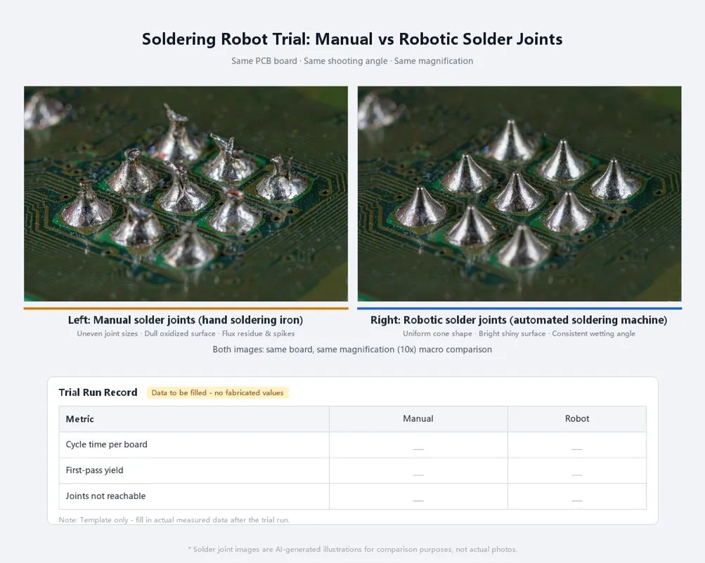
5. Note any joints the robot could not reach or could not solder well, so they are part of the decision.
To prepare a soldering trial, a supplier will usually need:
| Item | Why it is needed |
| Bare and assembled sample boards (or cables) | To build the fixture and test access to every joint |
| Joint list or marked drawing | Defines which joints are in scope and which stay manual |
| Solder wire specification (alloy, diameter, flux type) | Sets the starting temperature, feed and tip |
| Target output per shift | Decides single or dual platform, and how many machines |
| Quality criteria | For example, your internal standard or the IPC class you work to |
| Line layout (if in-line) | Board flow direction, conveyor height and available space |
If you are still deciding which back-end step to automate first, read. If your robot is already running and the joints are not right, our goes through each defect and the setting behind it. For the full range, see our automatic soldering machines.
RangJin Intelligent builds soldering robots, glue dispensers, potting machines and screw fastening machines in Dongguan, China. Our soldering machines are programmed by teaching, store programs for different products, and most models support both spot and drag soldering; the XH-AS4002Y also accepts coordinates imported from CAD (per product pages). Send us a board, your solder wire specification and your target output, and we will run a trial and send back joint close-ups and measured cycle times. Warranty and support terms are set out in each quotation. Contact our soldering team.
FAQ
Is a soldering robot faster than a skilled operator?
Not always per joint. A skilled operator can be quick on easy joints. The robot's advantage is that it keeps the same time, temperature and feed on every joint for a whole shift, and on a dual-platform machine the loading time is hidden. Measure cycle time per board in a trial on your own product before comparing.
Can a soldering robot replace selective wave soldering?
Sometimes. For boards with a limited number of top-side through-hole joints, a robot is often the simpler and lower-cost choice. For boards with many bottom-side through-hole joints at high volume, selective wave is usually the better process, and a robot would need too much time per board.
What volume justifies an automatic soldering machine?
There is no single threshold. Multiply joints per board by boards per shift, then compare your current labour and rework cost with the cost after automation using the worksheet above. Lines with steady repeat products and a shortage of skilled operators often reach a positive result at moderate volumes.
Can one robot handle several different PCB models?
Yes. Each board gets its own program and fixture. Programs are stored on the machine, so changing over means loading the program and swapping the fixture. Features such as program copying and point arrays shorten programming for similar boards.
What do you need from us to run a soldering trial?
Sample boards or cables, a list of the joints to be soldered, your solder wire specification, the output you need per shift and your quality criteria. With these, we can build a trial fixture and program and return joint close-ups and measured cycle times.
Associated Products
You may also be interested in the following products:
Inline Jet Dispensing Machine
CNC Glue Dispenser Machine
Silicone Dispenser Machine
SMT Glue Dispenser Machine
3-Axis Automated Glue Dispensing Machine
Automatic 3-Axis Hot Melt Glue Dispenser Machine
3 Axis AB Glue Dispenser Machine
Automatic Desktop 3 Axis UV Glue Dispenser
Benchtop 3 Axis Dispensing Robot
4 Axis 2 Part Epoxy Dispensing Equipment
Four Axis Industrial Glue Dispenser
4 Axis Benchtop Dispensing Robot
Five Axis Desktop Robotic Glue Dispenser
Desktop 5 Axis Glue Dispensing Robot
5-Axis Auto Glue Dispenser
5 Gallon Adhesive Supply Pump
High Speed Automatic Glue Dispensing Machine
3 Axis Automated Glue Dispenser
CCD Visual Glue Dispensing Machine